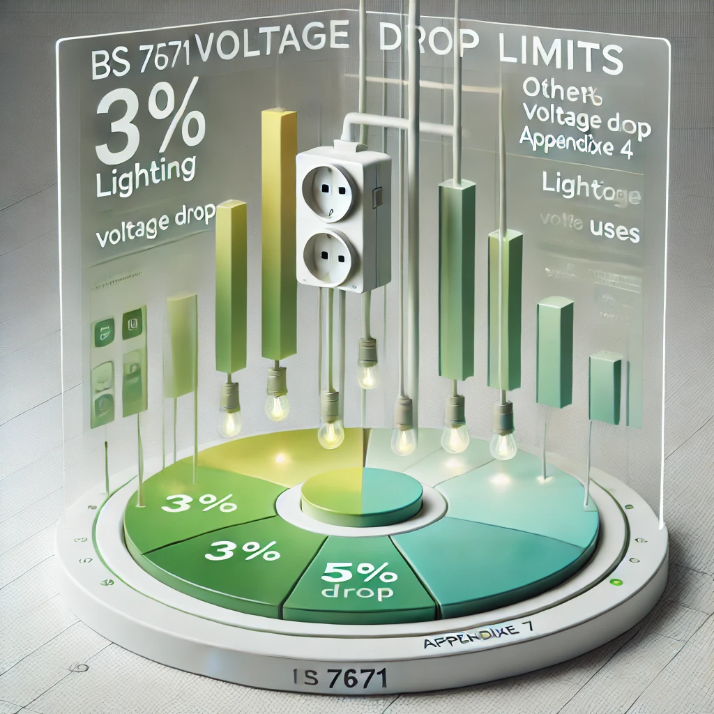
What Are the Limits for Voltage Drop in Electrical Installations?
Regulation 6.4 in BS 7671 Appendix 4 outlines the voltage drop limits for consumer installations, emphasizing the importance of managing voltage drop to ensure the safe and efficient operation of electrical equipment.

OW London Electrician and Home Automation Engineers Team
What Are the Limits for Voltage Drop in Electrical Installations?
Understanding voltage drop is crucial in electrical installations to ensure that equipment functions properly and safely. Excessive voltage drop can result in equipment malfunction, inefficiency, or even damage. Let us explore the regulation regarding voltage drop in consumer installations according to BS 7671.
Regulation 6.4 in BS 7671 Appendix 4 states:
"The voltage drop between the origin of an installation and any load point should not be greater than the values in the table below expressed with respect to the value of the nominal voltage of the installation.
- The calculated voltage drop should include any effects due to harmonic currents."
TABLE 4Ab – Voltage Drop
| Application | Lighting | Other Uses | ||
|---|---|---|---|---|
| Low Voltage | Low Voltage | |||
| (i) Installations supplied directly from a public LV system | 3% | 5% | ||
| (ii) Installations supplied from private LV supply (*) | 6% | 8% |
* The voltage drop within each final circuit should not exceed the values given in (i). Where the wiring systems of the installation are longer than 100 m, the voltage drops indicated above may be increased by 0.005% per meter of the wiring system beyond 100 m, without this increase being greater than 0.5%.*
The voltage drop is determined from the demand of the current-using equipment, applying diversity factors where applicable, or from the value of the design current of the circuit.
NOTES:
1. A greater voltage drop may be acceptable for a motor circuit during starting and for other equipment with a high inrush current, provided that in both cases the voltage variations remain within the limits specified in the relevant equipment standard.
2. The following temporary conditions are excluded:
- Voltage transients
- Voltage variations due to abnormal operation.
When designing electrical installations, it is essential to calculate and control voltage drop to stay within these limits. This ensures that all electrical equipment operates safely and efficiently, meeting the standards set forth by BS 7671.
Solved Examples of Voltage Drop Calculations
Example 1: Lighting Circuit Supplied from a Public Low Voltage System
Problem:
A 230V lighting circuit is supplied from a public low voltage distribution system. The total length of the circuit is 50 meters, and the design current of the circuit is 10A. Calculate the maximum allowable voltage drop and determine if a 4mm² copper conductor (with a resistance of 4.61 mΩ/m) is adequate.
Solution:
-
Step 1: Calculate the maximum allowable voltage drop.
- For lighting circuits supplied from a public low voltage system, the maximum voltage drop is 3%.
- Maximum voltage drop = 230V × 3% = 6.9V.
-
Step 2: Calculate the actual voltage drop using the formula:
-
Voltage Drop (V) = ( I \times R \times L ), where:
- ( I ) = current (10A),
- ( R ) = resistance per meter (4.61 mΩ/m or 0.00461 Ω/m),
- ( L ) = total length of the circuit (50m).
-
Voltage Drop = 10A × 0.00461 Ω/m × 50m = 2.305V.
-
-
Step 3: Compare the actual voltage drop with the maximum allowable voltage drop.
- Since 2.305V < 6.9V, the 4mm² copper conductor is adequate for this circuit.
Example 2: Power Circuit Supplied from a Private LV Supply
Problem:
A 400V power circuit for a motor is supplied from a private LV distribution system. The circuit length is 150 meters, and the design current is 20A. The motor has a high inrush current, so a slightly higher voltage drop is acceptable. Calculate the maximum allowable voltage drop and determine if a 6mm² aluminum conductor (with a resistance of 9.88 mΩ/m) is sufficient.
Solution:
-
Step 1: Calculate the maximum allowable voltage drop.
-
For power circuits supplied from a private LV system, the maximum voltage drop is 8%.
-
Since the wiring is longer than 100 meters, the voltage drop can be increased by 0.005% per meter beyond 100 meters.
-
Increase for additional length = (150m - 100m) × 0.005% = 0.25%.
-
Total allowable voltage drop = 8% + 0.25% = 8.25%.
-
Maximum voltage drop = 400V × 8.25% = 33V.
-
-
Step 2: Calculate the actual voltage drop using the formula:
-
Voltage Drop (V) = ( I \times R \times L ), where:
- ( I ) = current (20A),
- ( R ) = resistance per meter (9.88 mΩ/m or 0.00988 Ω/m),
- ( L ) = total length of the circuit (150m).
-
Voltage Drop = 20A × 0.00988 Ω/m × 150m = 29.64V.
-
-
Step 3: Compare the actual voltage drop with the maximum allowable voltage drop.
- Since 29.64V < 33V, the 6mm² aluminum conductor is sufficient for this circuit.
These examples illustrate how to apply the voltage drop regulations in practical scenarios to ensure that electrical installations comply with BS 7671 standards.

Frequently Asked Questions
Q: Why is it important to limit voltage drop in an installation?
A: Limiting voltage drop ensures that electrical equipment operates efficiently and safely. Excessive voltage drop can cause equipment to malfunction, operate inefficiently, or even become damaged. Regulation 6.4 in BS 7671 Appendix 4 specifies the maximum allowable voltage drop limits to prevent such issues.
What users Saying
Discover what our customers think about our services. Their feedback reflects our commitment to delivering exceptional service and expert solutions for all electrical and security needs.

