Understanding Reference Methods for Twin and Earth Cables in Thermal Insulation
This article breaks down the specific reference methods applicable to flat twin & earth cables installed in thermal insulation according to BS 7671, including Methods 100, 101, 102, 103, B, C, D, E, F, and G. Learn about different installation scenarios, key ratings, and precautions, ensuring compliance and safety in your electrical installations.
OW London Electrician and Home Automation Engineers Team
Reference Methods for Twin and Earth Cables
- Reference: Electrician’s Guide to the Building Regulations, Pages 36 and 37.
The following reference methods are applicable only to flat twin & earth cables when installed in thermal insulation. It is crucial to note that not all cable types are suitable for every Reference Method; for instance, flat twin and earth cables are not permitted to be installed directly in the ground.
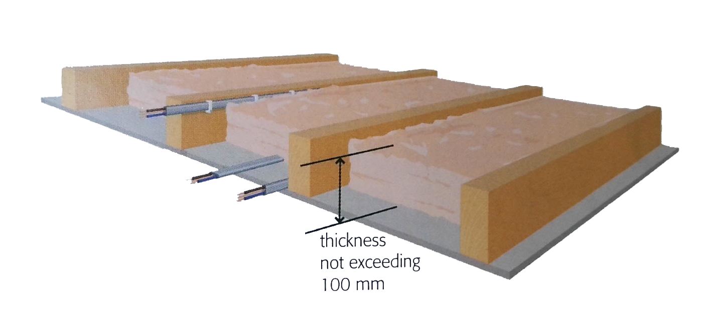
Reference Method 100
Description: Thermoplastic (polyvinylchloride – PVC) insulated and sheathed flat cables above a plasterboard ceiling where the cables are touching the ceiling or are clipped to a joist covered by thermal insulation not exceeding 100 mm.
Figure:
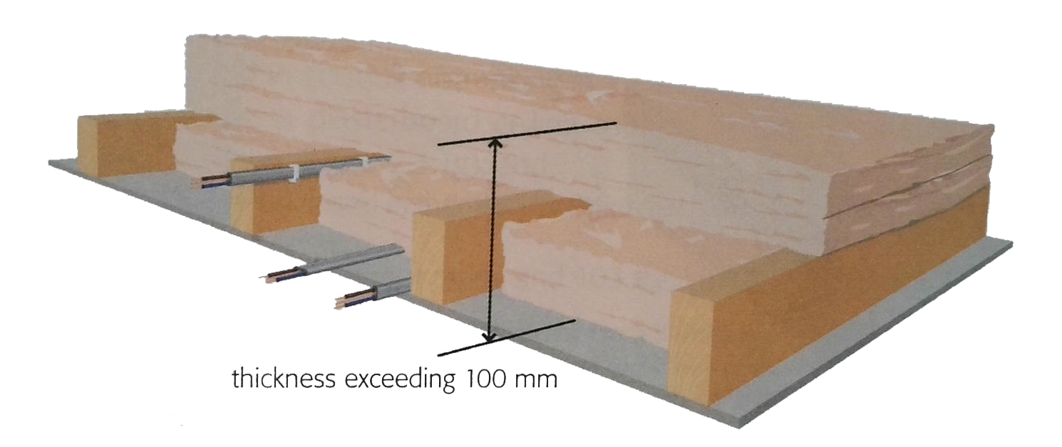
Reference Method 101
Description: Thermoplastic (PVC) insulated and sheathed flat cables above a plasterboard ceiling where the cables are touching the ceiling or are clipped to a joist covered by thermal insulation exceeding 100 mm.
Figure:
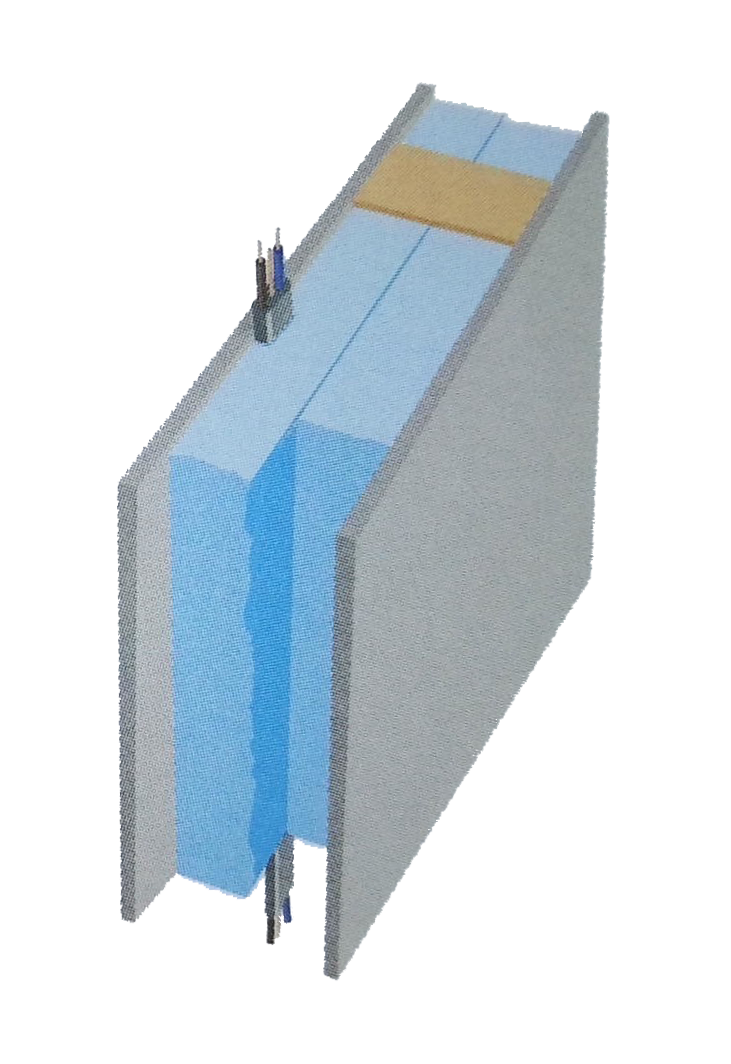
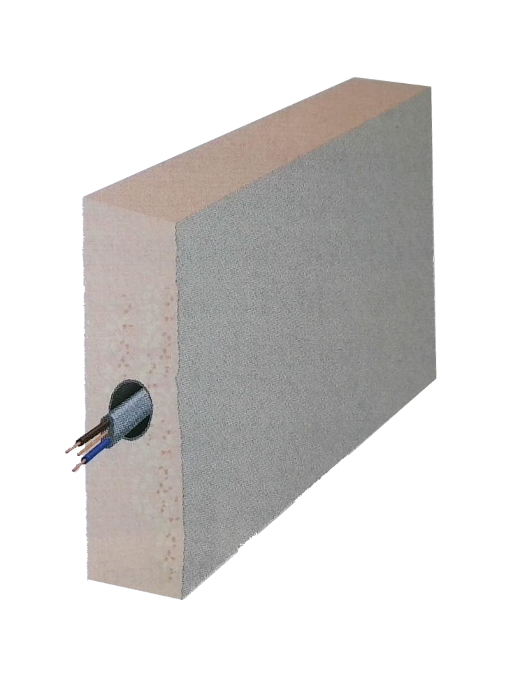
Reference Method 102
Description: Multicore thermoplastic insulated and sheathed flat twin cable with protective conductor in an insulating wall that is in contact with a thermally conductive surface on one side.
Figure:
Note: PVC sheathed cables should not come into contact with polystyrene insulation as it will degrade the sheath over a period of time.
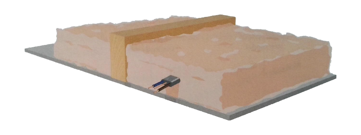
Reference Method 103
Description: If cables are surrounded by thermal insulation for less than 5 cm, no de-rating is necessary. Where cables are totally enclosed over a length of 0.5 m or more, the rating is half that for cables clipped directly to a conducting surface and unenclosed (reference method C).
Figure:
Note: It is preferable for the installation of cables to be so arranged that the cables are not totally enclosed.
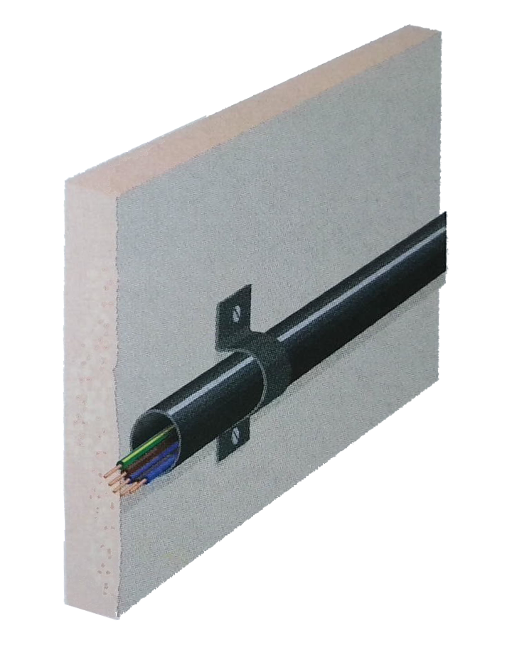
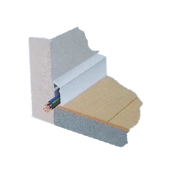
Reference Method B
Description: Cables installed in conduit inside a masonry wall or in trunking along ceilings and floors, ensuring the cables are insulated.
Figures:
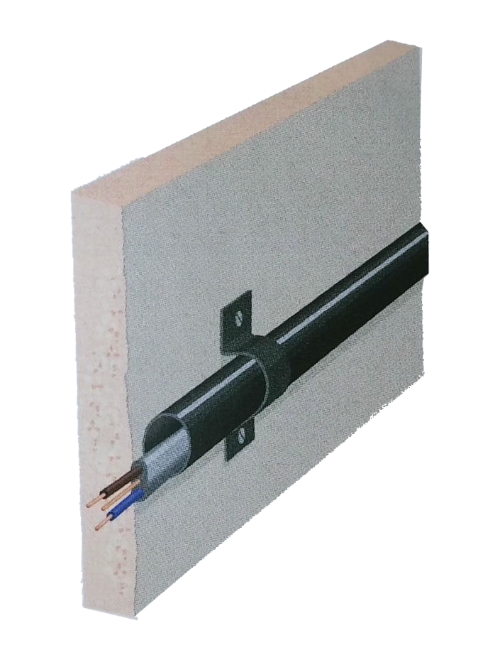
Reference Method C
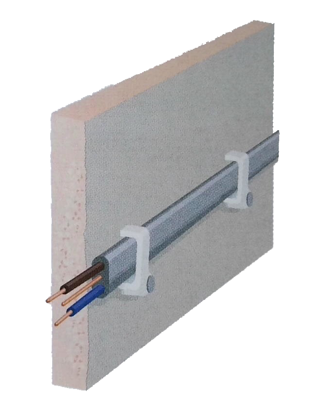
Description: Cables clipped directly to a surface or mounted on an unperforated cable tray. This method provides a straightforward installation but may require de-rating depending on the length of cable and the ambient temperature. Figure:
Cable Ratings (Table 2.3.1)
Source: From Table 4D5 of BS 7671
Description: Cable ratings (in amps) for 70 °C thermoplastic insulated and sheathed flat cables with a protective conductor.
Installation Reference Method Conductor Cross-Sectional Area (mm²) 1.0 C - Clipped direct 16 B - Enclosed in conduit or trunking 13 100 - In contact with plasterboard ceiling or joists covered by thermal insulation not exceeding 100 mm 13 102 - In a stud wall with thermal insulation with cable touching the wall 13 101 - In contact with plasterboard ceiling or joists, ceiling covered by thermal insulation exceeding 100 mm 13 103 - Surrounded by thermal insulation, including in a stud wall with thermal insulation, with cable not touching a wall 10
Additional Notes:
- Ensure that flat twin and earth cables adhere to the appropriate Reference Methods as stipulated by BS 7671, Table 4A2 and Table 4D5.
Reference: BS 7671 Appendix 4, Pages 430-433
7 METHODS OF INSTALLATION
Table 4A2 lists the methods of installation for which this appendix provides guidance for the selection of the appropriate cable size. Table 4A3 lists the appropriate tables for selection of current ratings for specific cable constructions. The Reference Methods are those methods of installation for which the current-carrying capacities given in Tables 4D1A to 4J4A have been determined (see 7.1 below).
The use of other methods is not precluded and in that case the evaluation of current-carrying capacity may need to be based on experimental work.
7.1 Reference Methods
The Reference Methods are those methods of installation for which the current-carrying capacity has been determined by test or calculation.
NOTE 1: It is impractical to calculate and publish current ratings for every installation method, since many would result in the same current rating. Therefore a suitable (limited) number of current ratings have been calculated which cover all of the installation methods stated in Table 4A2 and have been called Reference Methods.
Reference Method A, for example, Installation Methods 1 and 2 of Table 4A2 (non-sheathed cables and multicore cables in conduit in a thermally insulated wall).
The wall consists of an outer weatherproof skin, thermal insulation and an inner skin of wood or wood-like material having a thermal conductance of at least 10 W/m²K. The conduit is fixed such that it is close to, but not necessarily touching, the inner skin. Heat from the cables is assumed to escape through the inner skin only. The conduit can be metal or plastic.
Reference Method B, for example, Installation Method 4 of Table 4A2 (non-sheathed cables in conduit mounted on a wooden or masonry wall) and Installation Method 5 of Table 4A2 (multicore cable in conduit on a wooden or masonry wall).
The conduit is mounted on a wooden wall such that the gap between the conduit and the surface is less than 0.3 times the conduit diameter. The conduit can be metal or plastic. Where the conduit is fixed to a masonry wall the current-carrying capacity of the non-sheathed or sheathed cable may be higher.
Reference Method C (clipped direct), for example, Installation Method 20 of Table 4A2 (single-core or multicore cables on a wooden or masonry wall).
Cable mounted on a wooden wall so that the gap between the cable and the surface is less than 0.3 times the cable diameter. Where the cable is fixed to or embedded in a masonry wall the current-carrying capacity may be higher.
NOTE 2: The term 'masonry' is taken to include brickwork, concrete, plaster and similar (but excluding thermally insulating materials).
Reference Method D, for example, Installation Method 70 of Table 4A2 (multicore armoured cable in conduit or in cable ducting in the ground).
The cable is drawn into a 100 mm diameter plastic, earthenware or metallic duct laid in direct contact with soil having a thermal resistivity of 2.5 Km/W and at a depth of 0.7 m. The values given for this method are those stated in this appendix and are based on conservative installation parameters. If the specific installation parameters are known (thermal resistance of the ground, ground ambient temperature, cable depth), reference can be made to the cable manufacturer or the ERA 69-30 series of publications, which may result in a smaller cable size being selected.
NOTE 3: The current-carrying capacity for cables laid in direct contact with soil having a thermal resistivity of 2.5 Km/W and at a depth of 0.7 m is approximately 10% higher than the values tabulated for Reference Method D.
Reference Methods E, F, and G, for example, Installation Methods 31 to 35 of Table 4A (single-core or multicore cables in free air).
The cable is supported such that the total heat dissipation is not impeded. Heating due to solar radiation and other sources is to be taken into account. Care is to be taken that natural air convection is not impeded. In practice, a clearance between a cable and any adjacent surface of at least 0.3 times the cable external diameter for multicore cables or 1.0 times the cable diameter for single-core cables is sufficient to permit the use of current-carrying capacities appropriate to free air conditions.
7.2 Other Methods
Cable on a floor: Reference Method C applies for current rating purposes.
Cable under a ceiling: This installation may appear similar to Reference Method C but because of the reduction in natural air convection, Reference Method B is to be used for the current rating.
Cable tray systems: A perforated cable tray has a regular pattern of holes that occupy at least 30% of the area of the base of the tray. The current-carrying capacity for cables attached to perforated cable trays should be taken as Reference Method E or F. The current-carrying capacity for cables attached to unperforated cable trays (no holes or holes that occupy less than 30% of the area of the base of the tray) is to be taken as Reference Method C.
Cable ladder system: This is a construction which offers a minimum of impedance to the air flow around the cables, i.e., supporting surfaces occupy less than 10% of the plan area. The current-carrying capacity for cables on ladder systems should be taken as Reference Method E or F.
Cable cleats, cable ties and cable hangers: Cable supports hold the cable at intervals along its length and permit substantially complete free air flow around the cable. The current-carrying capacity for cable cleats, cable ties and cable hangers should be taken as Reference Method E or F.
Cable installed in a ceiling: This is similar to Reference Method A. It may be necessary to apply the rating factors due to higher ambient temperatures that may arise in junction boxes and similar mounted in the ceiling.
NOTE: Where a junction box in the ceiling is used for the supply to a luminaire, the heat dissipation from the luminaire may provide higher ambient temperatures than permitted in Tables 4D1A to 4J4A (see also Regulation 522.2.1). The temperature may be between 40 °C and 50 °C, and a rating factor according to Table 4B1 must be applied.
General notes to all tables in this appendix:
NOTE 1: Current-carrying capacities are tabulated for methods of installation which are commonly used for fixed electrical installations. The tabulated capacities are for continuous steady-state operation (100 % load factor) for DC or AC of nominal frequency 50 Hz and take no account of harmonic content.
NOTE 2: Table 4A2 itemizes the reference methods of installation to which the tabulated current-carrying capacities refer.
TABLE 4A1 – Schedule of Installation Methods in relation to conductors and cables: TABLE 4A1 – Schedule of Installation Methods in relation to conductors and cables:
Conductors and cables Without fixings Clipped direct Conduit systems Cable trunking systems* Cable ducting systems Cable ladder, cable tray, cable brackets On insulators Support wire Bare conductors np np np np np np P np Non-sheathed cable np np P¹ P¹² P np¹ P np Sheathed cables (including armouredand mineral insulated) Multicore P P P P P P N/A P Single-core N/A P P P P P N/A P P – Permitted.
np – Not permitted.
N/A – Not applicable, or not normally used in practice.Notes:
- Including skirting trunking and flush floor trunking.
- Non-sheathed cables which are used as protective conductors or protective bonding conductors need not be laid in conduits or ducts.
- Non-sheathed cables are acceptable if the trunking system provides at least the degree of protection IPXXD or IP4X and if the cover can only be removed by means of a tool or a deliberate action.
P – Permitted.
np – Not permitted.
N/A – Not applicable, or not normally used in practice.Notes:
- Including skirting trunking and flush floor trunking.
- Non-sheathed cables which are used as protective conductors or protective bonding conductors need not be laid in conduits or ducts.
- Non-sheathed cables are acceptable if the trunking system provides at least the degree of protection IPXXD or IP4X and if the cover can only be removed by means of a tool or a deliberate action.
Note: Table 4A2 details specific applications of the reference methods as various installation methods may be covered by the same reference method code.
What users Saying
Discover what our customers think about our services. Their feedback reflects our commitment to delivering exceptional service and expert solutions for all electrical and security needs.


