What Are the Maximum Disconnection Times in TN and TT Systems, and Why Does U0 Line-to-Earth Voltage Matter?
Regulation 411.3 of BS 7671 outlines the maximum disconnection times for TN and TT systems, emphasizing the importance of U0 line-to-earth voltage in ensuring safety. Understanding these requirements is crucial for minimizing the risk of electric shock and thermal damage in electrical installations.

OW London Electrician and Home Automation Engineers Team
What Are the Maximum Disconnection Times in TN and TT Systems, and Why Does U0 Line-to-Earth Voltage Matter?
The safety of an electrical installation heavily relies on the timely disconnection of circuits in the event of a fault. This ensures that any risk of electric shock or thermal damage is minimized. The regulations specify different maximum disconnection times depending on whether the system is TN (Terra Neutral) or TT (Terra Terra), and these times also vary according to the voltage U0, which is the nominal voltage between a line conductor and earth (L-E). Understanding the role of U0 is crucial, especially in three-phase systems where the line-to-line voltage (L-L) is higher, but the regulations focus on the line-to-earth voltage.
What is U0?
U0 is the nominal voltage between any line conductor (L) and earth (E). In single-phase systems, this is typically the same as the supply voltage. In three-phase systems, although the line-to-line (L-L) voltage is approximately 400V, U0 refers to the line-to-earth voltage, which is typically 230V. This distinction is important because the safety regulations, including disconnection times, are based on the potential difference between a single line conductor and earth, not between two line conductors.
Quoted Regulation and Table:
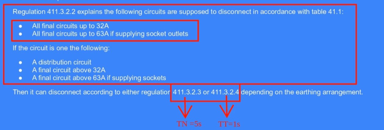
Regulation 411.3.2.2 states:
"The maximum disconnection times stated in Table 41.1 shall be applied to final circuits with a rated current not exceeding:
- (i) 63 A with one or more socket-outlets, and
- (ii) 32 A supplying only fixed connected current-using equipment."
Table 41.1 – Maximum Disconnection Times
The following table specifies the maximum disconnection times for TN and TT systems based on different ranges of U0 (L-E voltage). These times are critical for ensuring that protective devices, such as Residual Current Devices (RCDs) or overcurrent protective devices, operate within safe limits to prevent electric shock and thermal damage.
| System | 50 V < U0 ≤ 120 V | 120 V < U0 ≤ 230 V | 230 V < U0 ≤ 400 V | U0 > 400 V | ||||
|---|---|---|---|---|---|---|---|---|
| AC | DC | AC | DC | AC | DC | AC | DC | |
| TN | 0.8 s | NOTE 1 | 0.4 s | 1 s | 0.2 s | 0.4 s | 0.1 s | 0.1 s |
| TT | 0.3 s | NOTE 1 | 0.2 s | 0.4 s | 0.07 s | 0.2 s | 0.04 s | 0.1 s |
Detailed Interpretation:
System Types:
- TN System: In a TN system, the neutral and earth are connected at the source, providing a low-impedance path for fault currents. This reliable earthing allows for slightly longer disconnection times because the risk of prolonged exposure to a fault condition is lower.
- TT System: In a TT system, the earth connection is local to the installation and typically has a higher impedance than in a TN system. Due to this, disconnection times are shorter to ensure that any faults are quickly cleared, reducing the risk of electric shock.

Voltage Ranges and Corresponding Disconnection Times:
- 50 V < U0 ≤ 120 V:
- TN System: For AC circuits, the maximum disconnection time is 0.8 seconds. For DC circuits, refer to NOTE 1.
- TT System: For AC circuits, the maximum disconnection time is 0.3 seconds. For DC circuits, refer to NOTE 1.
- 120 V < U0 ≤ 230 V:
- TN System: For AC circuits, the maximum disconnection time is 0.4 seconds. For DC circuits, it is 1 second.
- TT System: For AC circuits, the maximum disconnection time is 0.2 seconds. For DC circuits, it is 0.4 seconds.
- 230 V < U0 ≤ 400 V:
- TN System: For AC circuits, the maximum disconnection time is 0.2 seconds. For DC circuits, it is 0.4 seconds.
- TT System: For AC circuits, the maximum disconnection time is 0.07 seconds. For DC circuits, it is 0.2 seconds.
- U0 > 400 V:
- TN System: The maximum disconnection time for both AC and DC circuits is 0.1 seconds.
- TT System: The maximum disconnection time for AC circuits is 0.04 seconds, and for DC circuits, it is 0.1 seconds.
Key Points from Notes:
- NOTE 1: In certain scenarios, disconnection is not required for electric shock protection but may still be necessary to prevent thermal effects such as overheating or potential fire hazards.
- NOTE 2: If compliance with these regulations is achieved using an RCD, the disconnection times in the table are relevant only to fault currents that are significantly higher than the rated residual operating current of the RCD. This ensures that RCDs trip quickly enough to protect against severe faults without nuisance tripping.
Additional Guidance for TT Systems:
In TT systems, when disconnection is achieved using an overcurrent protective device and all extraneous-conductive-parts are bonded as per Regulation 411.3.1.2, the disconnection times applicable to TN systems may be used. This allows certain TT installations, where bonding is comprehensive, to operate with the same disconnection time standards as TN systems, which generally have more lenient (longer) disconnection times due to their reliable earthing.
Frequently Asked Questions
Q: What does U0 represent, and why is it important in three-phase systems?
A: U0 represents the nominal voltage between any line conductor (L) and earth (E). In a three-phase system, the line-to-line L-L voltage is typically around 400V, but the line-to-earth L-E voltage, U0, is around 230V. The regulations, including disconnection times, focus on U0 because it is the voltage against which most safety considerations like the risk of electric shock are measured.
Q: Why are disconnection times shorter in TT systems compared to TN systems?
A: TT systems rely on local earthing, which can have higher impedance and therefore less reliable fault current paths than TN systems. Shorter disconnection times in TT systems ensure that faults are cleared quickly to minimize the risk of electric shock, as outlined in Regulation 411.3.2.4.
Q: Why might disconnection not be required for electric shock protection but still necessary for thermal effects?
A: In some scenarios, particularly where fault currents are low and unlikely to cause electric shock, disconnection might not be strictly necessary to protect against shock. However, even low fault currents can cause heating over time, potentially leading to fire or damage, so disconnection is required to prevent these thermal effects, as noted in Table 41.1.
Q: How do the disconnection times differ between low-voltage and high-voltage systems?
A: Disconnection times are generally shorter as the voltage increases:
- For example, in a TN system, the maximum disconnection time at 50V < U0 ≤ 120V is 0.8 seconds for AC, but at U0 > 400V, it drops to 0.1 seconds.
- In TT systems, disconnection times are even shorter, such as 0.3 seconds for 50V < U0 ≤ 120V and 0.04 seconds for U0 > 400V in AC circuits, as specified in Table 41.1.
Q: When can the TN system disconnection times be applied to TT systems?
A: TN system disconnection times can be applied to TT systems when the disconnection is managed by an overcurrent protective device, and all extraneous-conductive-parts are bonded according to Regulation 411.3.1.2. This scenario ensures the installation's earthing and bonding are robust enough to allow for the same disconnection time standards as TN systems, which generally have more lenient longer disconnection times.
Q: What is the impact of using an RCD on disconnection times?
A: When an RCD is used, the disconnection times in Table 41.1 apply only to fault currents significantly higher than the RCD’s rated residual operating current. This ensures the RCD will trip quickly enough to protect against dangerous faults while avoiding unnecessary tripping during minor faults.
By understanding and adhering to these disconnection times and voltage considerations, electrical installations can be designed to minimize the risk of electric shock and thermal damage, ensuring a safer environment for both people and equipment.

What users Saying
Discover what our customers think about our services. Their feedback reflects our commitment to delivering exceptional service and expert solutions for all electrical and security needs.

