Comprehensive Guide to Circuit Protection, Conductor Sizing, and Installation Heights for Switches and Emergency Controls as per BS 7671
Explore essential guidelines for circuit protection, conductor sizing, and the correct installation heights for switches, controllers, fire alarms, and emergency break glass panels according to BS 7671. This guide covers minimum conductor sizes, fuse requirements, and best practices for placing outlets, telephone points, and controls. Learn how to ensure safety and compliance with BS 7671 in your electrical installations, focusing on preventing hazards and avoiding unsafe practices like placing switches too low, which could force users to kneel.

OW London Electrician and Home Automation Engineers Team
Understanding Circuit Protection, Conductor Size, and Spurs According to BS7671
Regulation 433.1.204 states:
"For a 30 A or 32 A ring final circuit with a protective device in accordance with the requirements of Regulation 433.1.204, supplying 13 A socket-outlets to BS 1363, a conductor with a minimum cross-sectional area (csa) of 2.5 mm² is deemed to comply with the requirements of Regulation 433.1.1 if the current-carrying capacity (Iᵥ) of the cable is not less than 20 A and if, under the intended conditions of use, the load current in any part of the ring is unlikely to exceed for long periods the current-carrying capacity (Iᵥ) of the cable."
Circuit Protection
Table C1 from Guidance Note 1, Appendix C is relevant for circuits protected by fuses to BS 3036 and BS 88 and circuit-breakers Types B and C to BS EN 60898 or BS EN 61009-1 and BS EN 60947-2, as well as Types 1, 2, and 3 to BS 3871.
Conductor Size
The minimum size of conductors in the circuit and in non-fused spurs is specified in Table C1. However, in situations where more than two circuits are bunched together or the ambient temperature exceeds 30°C, the conductor size must be increased. This increase is determined by applying the appropriate rating factors from Appendix 4 of BS 7671, ensuring the size corresponds to a current-carrying capacity of not less than:
- 20 A for a ring circuit A1.
- 30 A or 32 A for a radial circuit A2.
- 20 A for a radial circuit A3.
For fused spurs, the conductor size depends on the total current demand, limited to a maximum of 13 A. For socket-outlets, the minimum conductor size is 1.5 mm² for thermoplastic (PVC) or thermosetting insulated cables, and 1 mm² for mineral insulated cables.
Spurs
The number of fused spurs is unlimited, but non-fused spurs must not exceed the total number of socket-outlets and items of stationary equipment directly connected to the circuit.
Placement of Outlets, Switches, and Controls
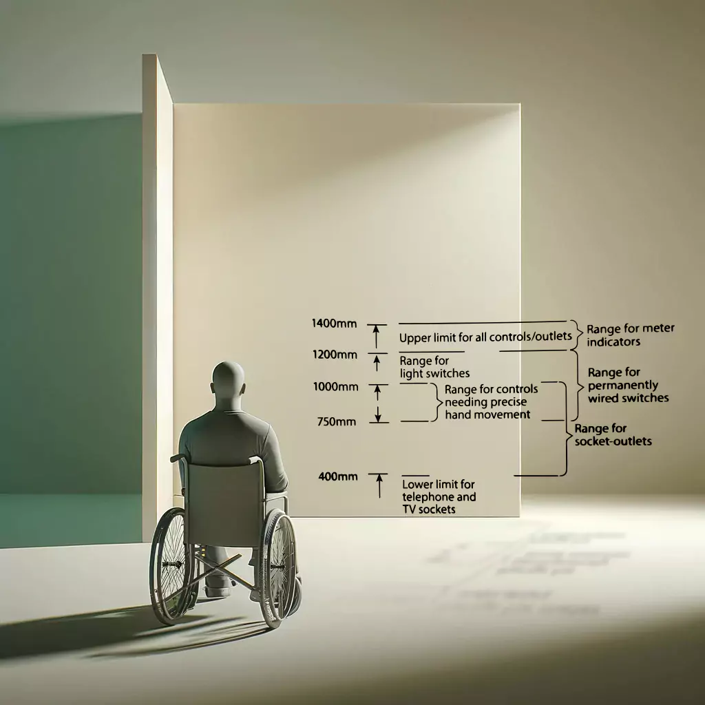
According to BS 8300-2:2018, all outlets, switches, and controls should be positioned consistently in relation to doorways and corners within a building. For ease of use, light switches should align horizontally with door handles. Electrical wall sockets, telephone points, and television/data sockets should be located at least 400 mm but not more than 1000 mm above the floor. The maximum height for all controls and outlets is 1400 mm.

- 1400 mm: Upper limit for all controls/outlets.
- 1200 mm: Range for meter indicators.
- 1200 mm: Range for light switches.
- 1000 mm: Range for controls needing precise hand movement.
- 750 mm: Range for socket-outlets.
- 400 mm: Lower limit for telephone and TV sockets.
Frequently Asked Questions
Q: What types of circuit protection are applicable for different circuit-breakers?
A: According to Guidance Note 1, Appendix C, page 161, Table C1 is applicable for circuits protected by fuses to BS 3036 and BS 88, and circuit-breakers, Types B and C to BS EN 60898 or BS EN 61009-1 and BS EN 60947-2, and Types 1, 2, and 3 to BS 3871.
Q: How should the conductor size be determined when multiple circuits are bunched together or ambient temperatures exceed 30°C?
A: Per Guidance Note 1, Appendix C, page 161, if the cables of more than two circuits are bunched together or the ambient temperature exceeds 30°C, the conductor size should be increased by applying the appropriate rating factors from Appendix 4 of BS 7671. The size must correspond to a current-carrying capacity not less than 20 A for ring circuit A1, 30 A or 32 A for radial circuit A2, and 20 A for radial circuit A3.
Q: What are the minimum conductor sizes for fused spurs serving socket-outlets?
A: Guidance Note 1, Appendix C, page 161 specifies that the minimum conductor size for a fused spur serving socket-outlets is 1.5 mm² for thermoplastic (PVC) or thermosetting insulated cables with copper conductors, and 1 mm² for mineral insulated cables with copper conductors.
Q: How does BS 7671 ensure the protection of electrical accessories from high operating temperatures?
A: As per Guidance Note 1, Appendix C, page 161, electrical accessories designed for use with thermoplastic (PVC) insulated conductors must comply with the maximum operating temperature requirements. If thermosetting or mineral insulated cables are used, they must be derated according to Table 4E2A of Appendix 4 in BS 7671 to prevent damage to the accessories.
Q: What are the installation height requirements for outlets, switches, and controls within a building?
A: According to Guidance Note 1, Appendix C, page 161, outlets, switches, and controls should be positioned between 400 mm and 1200 mm above the floor, with emergency ‘break glass’ panels and door releases mounted between 1000 mm and 1200 mm from the floor. The maximum height for meter indicators is 1400 mm.
What users Saying
Discover what our customers think about our services. Their feedback reflects our commitment to delivering exceptional service and expert solutions for all electrical and security needs.

